September 18, 2021
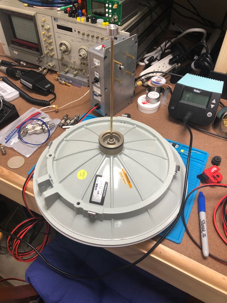
Started working on the first dish - below I am measuring the brass tubing which is being used as circular waveguide for the the stock chaparral feed mount. The units will mount to the back of the dishes. The excessive length on the brass tubing will be removed once I complete the measurements.
September 17, 2021
Unit #2 before closing it up. Both units complete except A/B switch connection.
September 10, 2021
Unit 1 on left and unit 2 on right
September 9, 2021
Working on unit #2
Above - 1st unit RX - 2nd unit TX.
Below - 2nd unit TX below and being built.
September 5, 2021
Working on the case for unit #2
September 3, 2021
The CW sounds better now - I changed the filter 3 setting on the IC-705 IF radio.
Finally success in TX/RX - I had to point the two units directly at each other - one has the conical horn (RX) and the other has the chaparral feed (TX). This was before I tuned the filter 3 on my IC-705 radio - see better results above.
August 31, 2021
Started working on second unit yesterday.
August 29, 2021
Did the same 10MHz mod to my first board as VA3TO. I no longer need the 1PPS source.
VA3TO Mod on his board below.
August 26, 2021
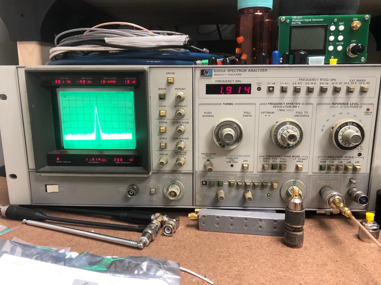
Checked the VCO Test Point and received the expected 1.914GHz on the first unit.
August 26, 2021
Everything so far setup and tested except the reset or the channel A/B switch. I have tested the PTT and the key and beacon mode - all testing good. I am waiting on info to do the 10MHz modification and then this first unit will almost be complete except the reset and channel A/B switch.
August 24, 2021
August 21, 2021
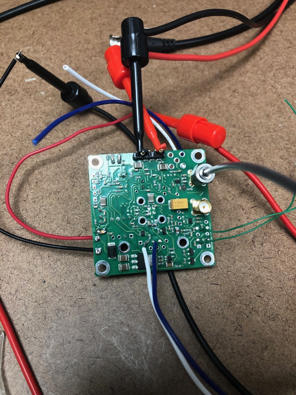
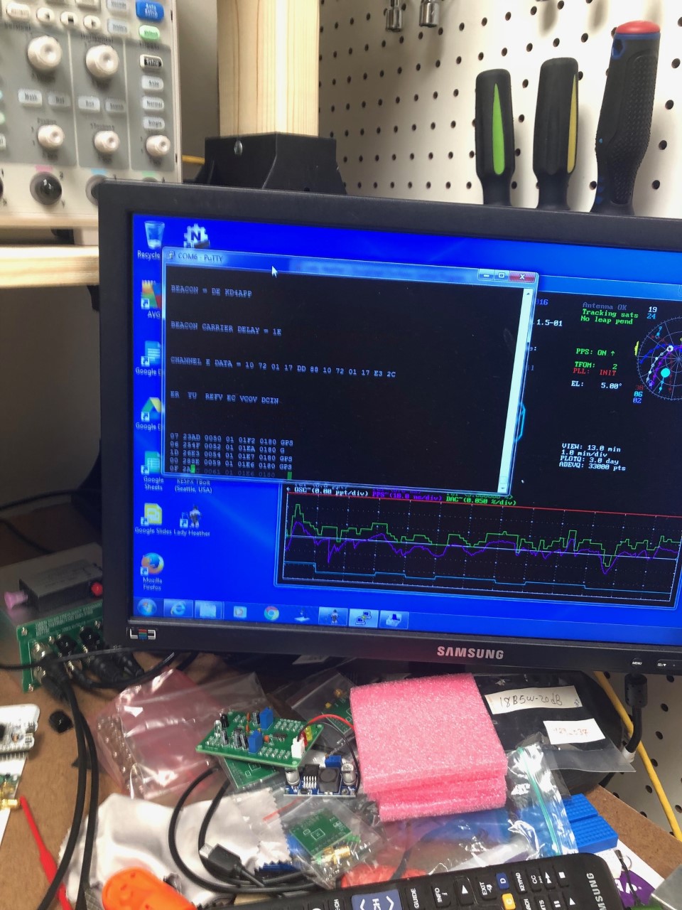
I have my first unit connected to power, 1PPS, serial RX/TX and the 10MHz out connected to my SA. I see the light on and I'm getting a 10MHz signal from the board.
Seeing the boot messages and the GPS info.
The red and black mini-grabbers connecting to the GPS header are supplying 1PPS from my GPSDO.
In the first picture you see the power wires near the bottom of the picture.
Tests successful so far.
Serial tests below
My units arrived - August 18, 2021
Progress on case - June 1, 2021
Waiting on my boards to arrive - working on the case for the first board.
Inside - above
Left ( <- top) - above
Right (top -> ) - above
Top - above